Product Description
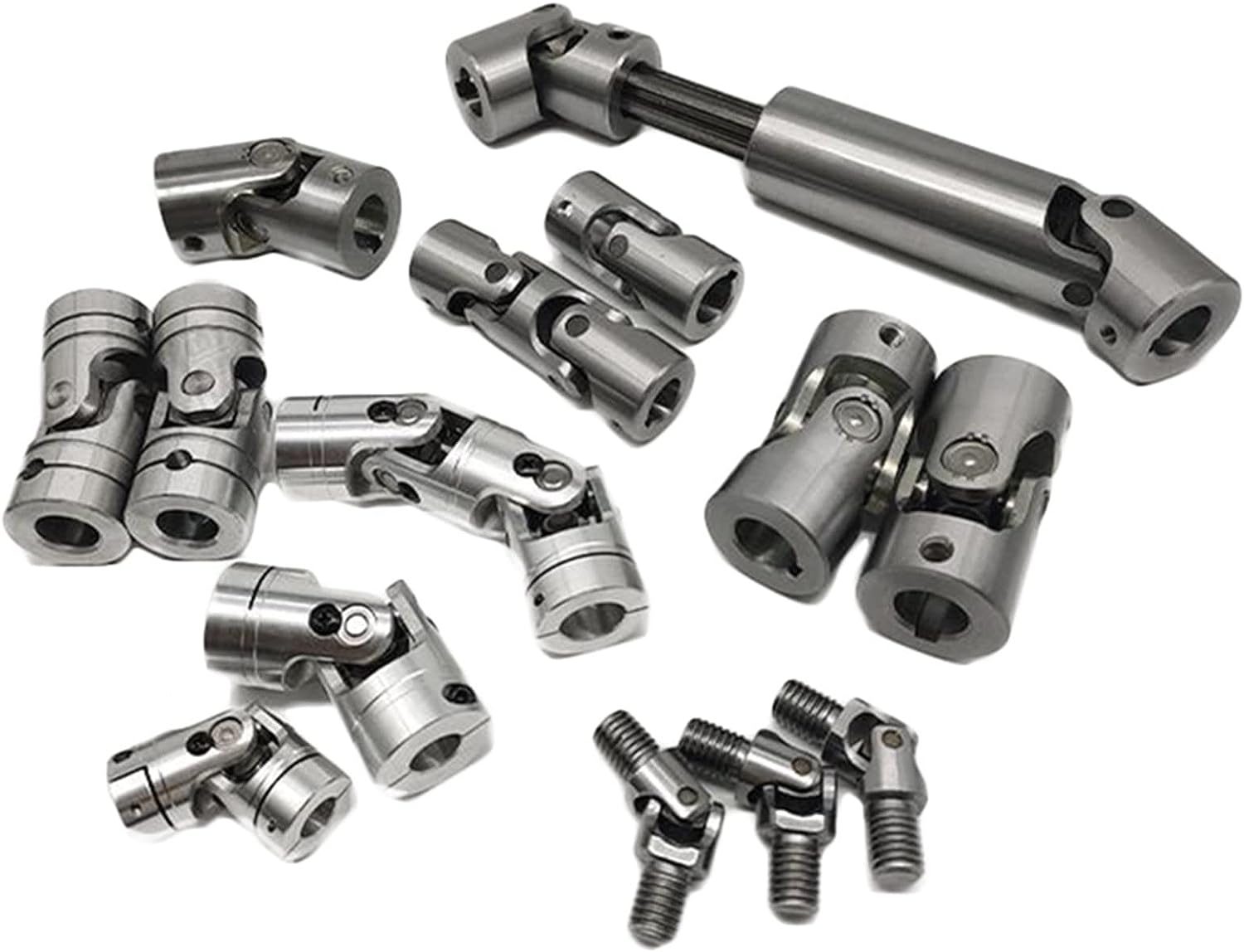
HangZhou Xihu (West Lake) Dis. universal shafts Co.,LTD is a leading professional manufacturer of cardan shafts in China. It is located in HangZhou ,ZheJiang Province. Our company has focused on the research and development , design and manufacture with different kinds of cardan shafts for almost 15 years.
Our producted cardan shafts are widely used in domestic large steel enterprises, such as ZheJiang Baosteel, HangZhou Iron and Steel Corporation, HangZhou Steel Corp and other domestic large-scale iron and steel enterprises.Now more products are exported to Europe, North America and Southeast Asia and other regions.
Our cardan shafts can be used to resist vibration and impact in the harsh environment of steel rolling, and the service life of cardan shafts is longer. We can also customize the special connection modes of cardan shafts in accordance of customers’ requirements .High precision, flexible joints, easy installation, perfect after-sales service and so on are highlight features of our products.
SWC-I Series-Light-Duty Designs Cardan shaft
Designs
Data and Size of SWC-I Series Universal Joint Couplings
| Type | Desian Data Item |
SWC-I 58 |
SWC-I 65 |
SWC-I 75 |
SWC-I 90 |
SWC-I 100 |
SWC-I 120 |
SWC-I 150 |
SWC-I 180 |
SWC-I 200 |
SWC-I 225 |
| A | L | 255 | 285 | 335 | 385 | 445 | 500 | 590 | 640 | 775 | 860 |
| Lv | 35 | 40 | 40 | 45 | 55 | 80 | 80 | 80 | 100 | 120 | |
| m(kg) | 2.2 | 3.0 | 5.0 | 6.6 | 9.5 | 17 | 32 | 40 | 76 | 128 | |
| B | L | 150 | 175 | 200 | 240 | 260 | 295 | 370 | 430 | 530 | 600 |
| m(kg) | 1.7 | 2.4 | 3.8 | 5.7 | 7.7 | 13.1 | 23 | 28 | 55 | 98 | |
| C | L | 128 | 156 | 180 | 208 | 220 | 252 | 340 | 348 | 440 | 480 |
| m(kg) | 1.3 | 1.95 | 3.1 | 5.0 | 7.0 | 12.3 | 22 | 30 | 56 | 96 | |
| Tn(N·m) | 150 | 200 | 400 | 750 | 1250 | 2500 | 4500 | 8400 | 16000 | 22000 | |
| Tf(N·m) | 75 | 100 | 200 | 375 | 630 | 1250 | 2250 | 4200 | 8000 | 11000 | |
| β(°) | 35 | 35 | 35 | 35 | 35 | 35 | 35 | 25 | 25 | 25 | |
| D | 52 | 63 | 72 | 92 | 100 | 112 | 142 | 154 | 187 | 204 | |
| Df | 58 | 65 | 75 | 90 | 100 | 120 | 150 | 180 | 200 | 225 | |
| D1 | 47 | 52 | 62 | 74.5 | 84 | 101.5 | 130 | 155.5 | 170 | 196 | |
| D2(H9) | 30 | 35 | 42 | 47 | 57 | 75 | 90 | 110 | 125 | 140 | |
| D3 | 38 | 38 | 4 | 50 | 60 | 70 | 89 | 102 | 114 | 140 | |
| Lm | 32 | 39 | 45 | 52 | 55 | 63 | 85 | 87 | 110 | 120 | |
| k | 3.5 | 4.5 | 5.5 | 6.0 | 8.0 | 8.0 | 10.0 | 12.0 | 14.0 | 15.0 | |
| t | 1.5 | 1.7 | 2.0 | 2.5 | 2.5 | 2.5 | 3.0 | 4.0 | 4.0 | 5.0 | |
| n | 4 | 4 | 6 | 4 | 6 | 8 | 8 | 8 | 8 | 8 | |
| d | 5.1 | 6.5 | 6.5 | 8.5 | 8.5 | 10.5 | 13 | 15 | 17 | 17 | |
| MI(kg) | 0.14 | 0.16 | 0.38 | 0.38 | 0.53 | 0.53 | 0.87 | 0.87 | 1.65 | 2.14 | |
| Flange bolt | size | M5 | M6 | M6 | M8 | M8 | M10 | M12 | M14 | M16 | M16 |
| Tightening torque(N·m) | 7 | 13 | 13 | 32 | 32 | 64 | 110 | 180 | 270 | 270 |
1. Notations:
L=Standard length, or compressed length for designs with length compensation;
LV=Length compensation;
M=Weight;
Tn=Nominal torque(Yield torque 50% over Tn);
TF=Fatigue torque, I. E. Permissible torque as determined according to the fatigue strength
Under reversing loads;
β=Maximum deflection angle;
MI=weight per 100mm tube
2. Millimeters are used as measurement units except where noted;
3. Please consult us for customizations regarding length, length compensation and
Flange connections.
Brief Introduction
Processing flow
Applications
Quality Control
/* March 10, 2571 17:59:20 */!function(){function s(e,r){var a,o={};try{e&&e.split(“,”).forEach(function(e,t){e&&(a=e.match(/(.*?):(.*)$/))&&1
Recent Technological Advancements in Cardan Coupling Design
In recent years, there have been notable advancements and innovations in the design of cardan couplings:
- Material Enhancements: Advances in materials science have led to the development of high-strength and lightweight materials that can improve the performance and durability of cardan couplings.
- Sealing Technology: Improved sealing mechanisms and materials help prevent contamination and enhance the lifespan of cardan couplings.
- Computer-Aided Design (CAD): CAD software allows for more precise and optimized design of cardan couplings, leading to better performance and reduced stress concentrations.
- Finite Element Analysis (FEA): FEA techniques enable engineers to simulate the behavior of cardan couplings under various loads and conditions, aiding in design optimization.
- Lubrication Systems: Innovations in lubrication systems ensure efficient and consistent lubrication, reducing wear and enhancing coupling longevity.
- Monitoring and Diagnostics: Integration of sensors and monitoring systems enables real-time data collection for performance analysis, predictive maintenance, and early detection of issues.
- Customization: Advanced manufacturing techniques allow for more customization, making it possible to design cardan couplings tailored to specific applications.
These advancements contribute to the overall efficiency, reliability, and performance of cardan couplings, making them more suitable for a wide range of applications.
Comparison of Cardan Couplings with Other Flexible Couplings
Cardan couplings, universal joints, and gear couplings are all types of flexible couplings used to transmit torque while accommodating misalignment. Here’s how a cardan coupling compares to other flexible coupling types:
1. Cardan Couplings:
– Also known as shaft couplings or u-joints.
– Typically consist of two yokes connected by a cross-shaped component called a spider.
– Accommodate angular misalignment.
– Limited to relatively lower speeds and torques.
– Provide moderate torsional flexibility.
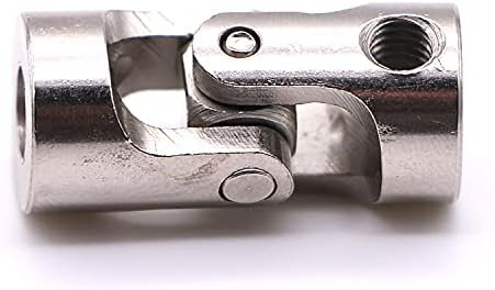
2. Universal Joints:
– Consist of two yokes connected by cross-shaped pins and bearings.
– Accommodate angular misalignment similar to cardan couplings.
– Can transmit higher torques than cardan couplings.
– Limited in their ability to handle axial and parallel misalignment.
– Used in various applications, including automotive and industrial equipment.
3. Gear Couplings:
– Feature toothed gears that mesh to transmit torque.
– Accommodate angular, axial, and parallel misalignment.
– Suitable for high-speed and high-torque applications.
– Provide high torsional rigidity and accurate torque transmission.
– Require proper lubrication and maintenance.
When comparing these coupling types:
– Cardan couplings are simple and cost-effective solutions for moderate torque and speed applications with angular misalignment.
– Universal joints are versatile but may have limitations in handling higher torques and other misalignment types.
– Gear couplings offer superior torque and misalignment handling but are more complex and may require more maintenance.
The choice of coupling type depends on the specific application’s torque, speed, misalignment, and precision requirements.
Accommodation of Angular Misalignment in Shaft with Cardan Coupling
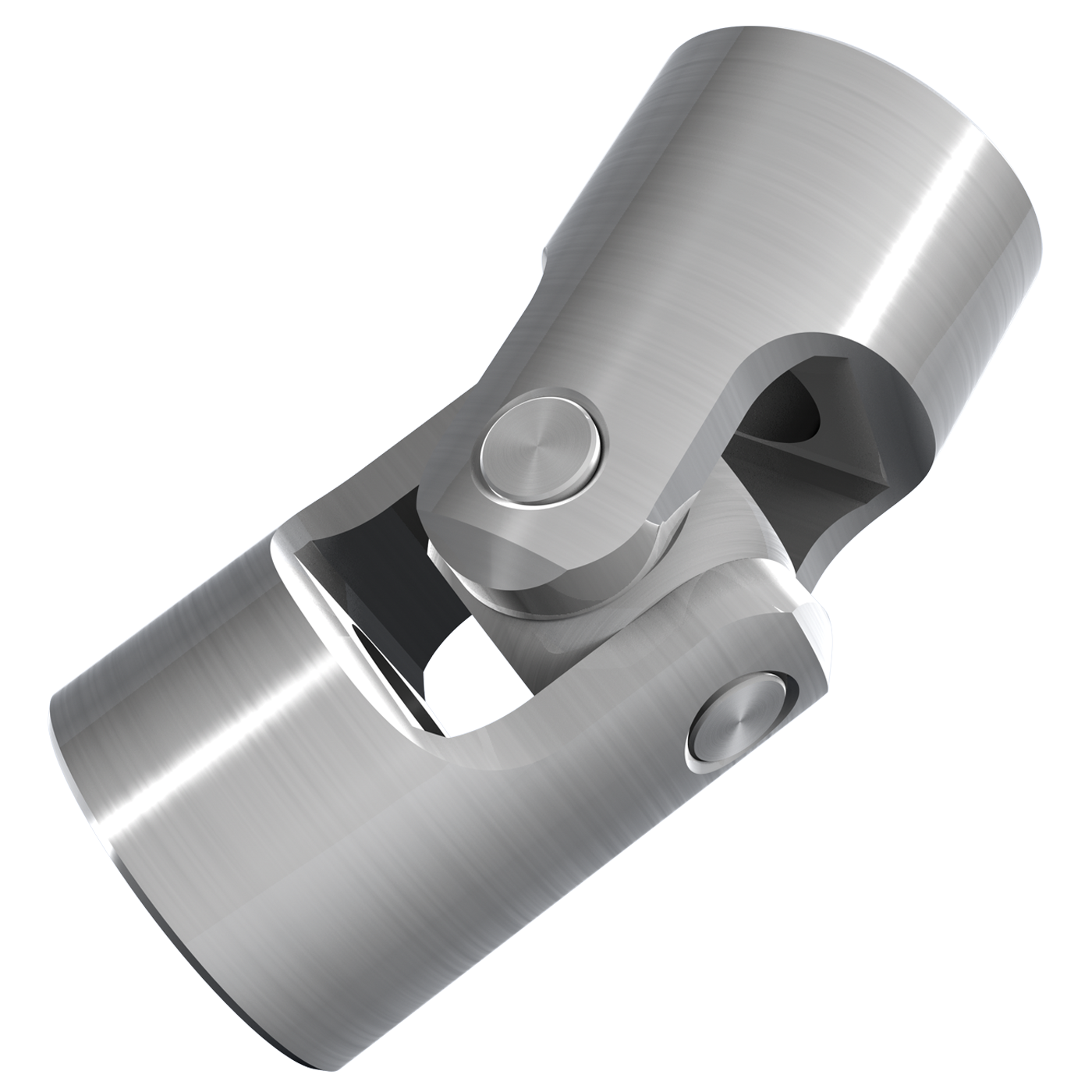
A cardan coupling, also known as a universal joint or u-joint, is designed to accommodate angular misalignment between two shafts while maintaining a constant velocity transfer. Here’s how it works:
The cardan coupling consists of two yokes or fork-like components, each attached to the end of a shaft. These yokes are connected by a cross-shaped central component called the cross or spider. The spider has bearings at its four ends that fit into grooves in the yokes.
When the connected shafts are misaligned at an angle, the spider allows the yokes to pivot around their respective shafts. This pivoting action of the yokes and the spider enables the coupling to transmit torque between the shafts even when they are not perfectly aligned. The spider’s bearings allow smooth rotation and transfer of power.
The design of the cardan coupling ensures that even during angular misalignment, the rotational speed remains consistent between the input and output shafts. However, it’s important to note that while cardan couplings can accommodate angular misalignment, they introduce a small amount of radial and axial movement, which can lead to fluctuating torque and vibration.
Cardan couplings are commonly used in applications where there is a need to transmit torque between shafts that are not in line, such as in drivetrains, vehicle suspensions, and industrial machinery.


editor by CX 2024-02-11