Method
S-Flex Coupling Assortment Approach
The variety procedure for identifying the right S-Flex coupling needs employing the charts proven within the following pages. You’ll find three parts for being picked, two flanges and one sleeve.
Details necessary just before a coupling can be selected:
HP and 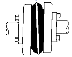 RPM of Driver or working torque
Shaft dimension of Driver and Driven gear and corresponding keyways
Application or gear description
Environmental ailments (i.e. severe temperature, corrosive conditions, area limitations)
Ways In Selecting An S-Flex Coupling
Step 1: Figure out the Nominal Torque in in-lb of one’s application through the use of the following formula:
Nominal Torque = (HP x 63025)/RPM
Step 2: Making use of the Application Service Component Chart 1 pick the support aspect which best corresponds for your application.
Stage three: Determine the Layout Torque of the application by multiplying the Nominal Torque calculated in Stage 1 from the Application Service Aspect determined in Stage two.
Layout Torque = Nominal Torque x Application Services Factor
Stage 4: Applying the Sleeve Functionality Information Chart 2 pick the sleeve materials which most effective corresponds to your application.
Stage five: Employing the S-Flex Nominal Rated Torque Chart 3 find the suitable sleeve material column for that sleeve chosen in Phase 4.
Stage 6: Scan down this column for the initially entry the place the Torque Value during the column is higher than or equal to your Style Torque calculated in Step 3.
Refer towards the highest RPM worth from the coupling size to make sure the application demands are met. When the maximum RPM worth is less than the application requirement, S-Flex couplings aren’t proposed for the application.
Note:
If Nominal Torque is less than 1/4 of the coupling’s nominalrated torque, misalignment capacities are reduced by 1/2. When torque worth is found, refer for the corresponding coupling dimension from the to start with column of the S-Flex Nominal Rated Torque Data Chart three .
Stage seven: Examine the application driver/driven shaft sizes towards the greatest bore dimension obtainable over the coupling picked. If coupling max bore isn’t big ample for the shaft diameter, pick the following largest coupling which will accommodate the driver/driven shaft diameters.
Stage 8: Making use of the Item Selection tables, uncover the ideal Keyway and Bore size demanded and locate the variety.