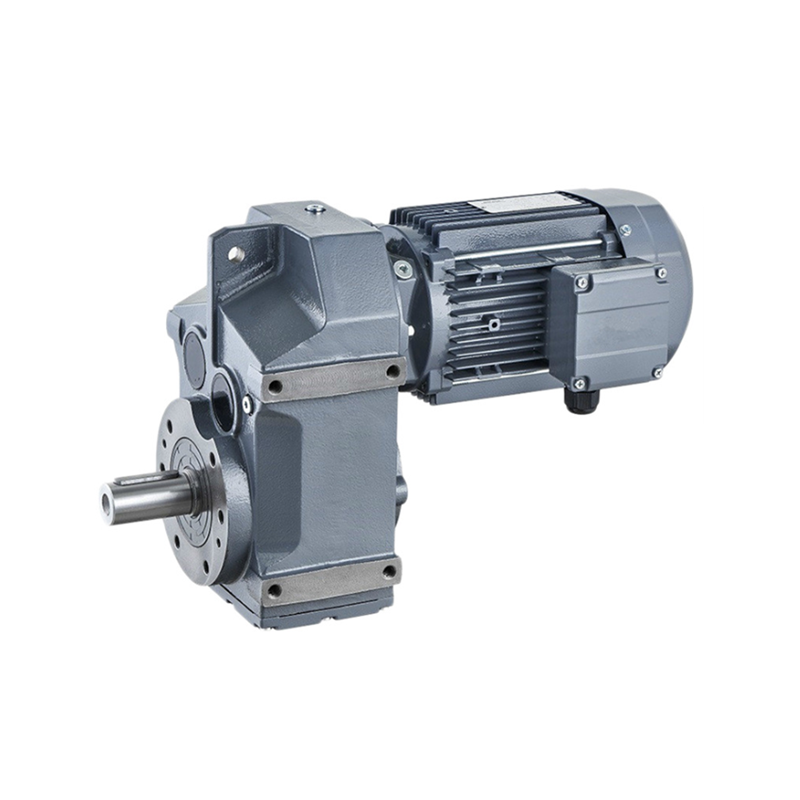
Observing several principles for proper installation is essential to the trusted and appropriate operation with the gearbox or gear motor.
The guidelines set out here are meant as a preliminary manual to picking out gearbox or gear motor. For effective and correct set up, observe the instructions provided from the installation, make use of the maintenances guide for the gearbox readily available from our sales division.
Following is usually a short outline of set up rules:
a) Fastening:
Place gearbox on a surface supplying ample rigidity. Mating surfaces ought to be machined and flat.
Mating surfaces have to be inside definite geometric tolerances (see manual). That is primarily accurate of flange-mounted gearboxes with splined hollow shafts.
In applications that involve large radial loads in the output finish, flange mounting is recommended for some gearbox sizes as this mounting can make utilization of the double pilot diameters offered in these gearboxes.
Make certain the gearbox is appropriate to the demanded mounting place.
Use screws of resistance class 8.8 and more than to secure the gearbox. Torque up screws for the figures
indicated during the relevant tables.
With transmitted output torque greater than or equal 70% with the indicated M2max  torque, and with
frequent movement reversals, use screws with minimum resistance 10.9.
Some gearbox sizes could be fastened utilizing both screws or pins. Of pin seated in the frame the gearboxes be not less than one.5 times pin diameter.
b) Connections
Safe the connection parts to gearbox input and output. Usually do not tap them with hammers or related resources.
To insert these parts, make use of the support screws and threaded holes presented about the shafts. You’ll want to clean off any grease or protects through the shafts just before fitting any connection elements.
Fitting hydraulic motors.
Be careful the O ring concerning motor flange and gearbox input flange when assembling. Install the
hydraulic motor ahead of filling lube oil into the gearbox.
Connecting the hydraulic brake.
The hydraulic circuit needs to be such to be sure that brake is released instants in advance of gearbox begins and utilized immediately after gearbox has stopped. Check out that strain within the hydraulic line for brake release is at zero every time gearbox is stopped.
Route of rotation
Motors are linked to your appropriate electric or hydraulic circuit as outlined by their course of rotation.
When executing these connections, keep in mind that all gearboxes, whether in the in-line or ideal angle design and style, have the identical path of rotation each at input and output. For much more particulars on the connection of electrical and hydraulic motors, see related sections within this catalogue.
